
1962
Bentley S2
Ypsilanti, Michigan
Part I - Brakes and Engine Prep
 |
December
11, 2009 We have a new addition to the family as well as a new long term project. This is a 1962 Bentley S2. She is a B-series car built in 1960 but purchased new from J.S. Inskip in New York in the fall of 1962 and registered as a 1962 model to the first owner in Cincinnati. We used the Dodge Ram truck to disinter the Bentley from the lower garage of the previous owner. We used all 360 cubic inches and every last bit of available traction. |
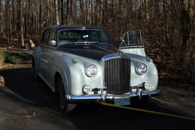 |
As you can see it is left hand drive. It was factory prepared for air conditioning (i.e., tinted glass, insulated cabin, and underhood plumbing) with CoolAir unit in the left hand wing installed by Inskip more typically seen on the Silver Cloud III and S3. This is arguably the most effective period air conditioning setup. Other options include electric windows and a tachometer. |
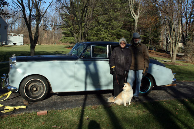 |
This is Theresa, Theresa's son Al and Sadie the dog. Theresa's late husband Willard bought the car in 1971 and was most likely the third owner. The car has not been started in 15 years and three of the four brakes had seized. I do not yet know if the engine will turn freely. The plan is to squirt sewing machine oil into the cylinders and allow that to soak in while I overhaul the brakes. |
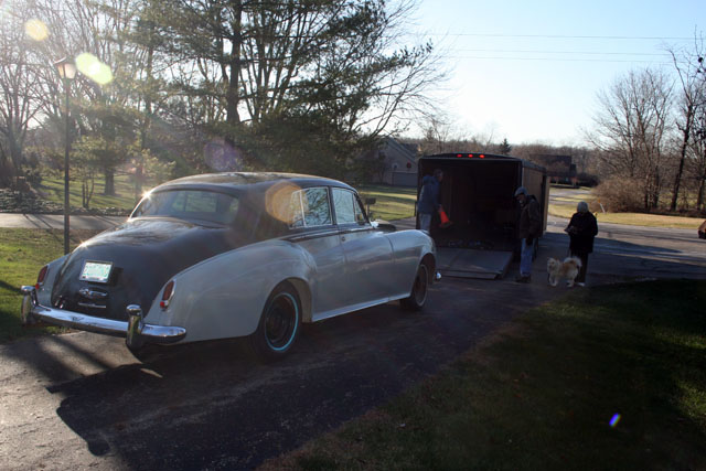 |
The rear tires were flat and would not hold air. I retrieved those two last week, had the rims powder coated and then mounted new radial tires. The front wheels and spare will receive the same treatment over the holidays. |
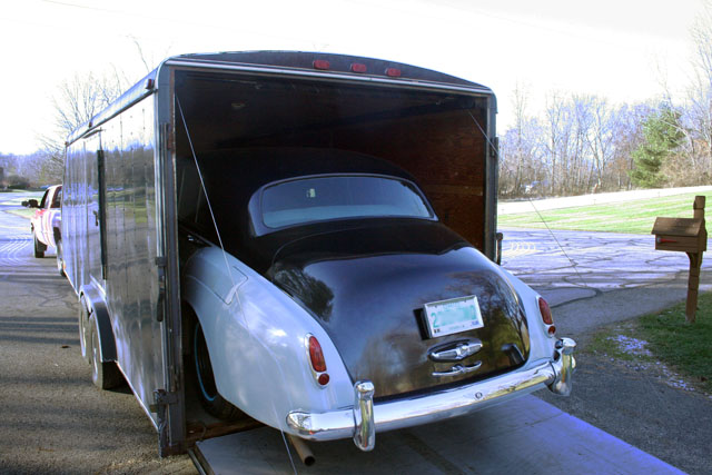 |
Almost ready to set sail from suburban Columbus to Ypsilanti, Michigan. Roy's 26-foot trailer is really nice to pilot down the highway. The torsion bars do a nice job of enhancing the stability and the brakes work well. The combined weight does capture the full attention of the truck on the highway. Expect 6-8 mpg. |
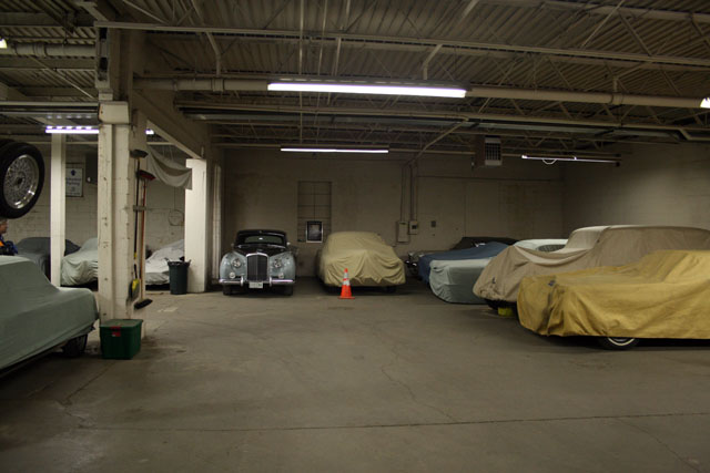 |
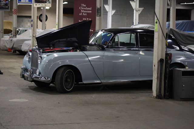
8:15 PM Safely nestled in her new home somewhere in Ypsilanti. This co-op is where I keep the two Rolls-Royces as well. The Wraith is the tall one second from the right. |
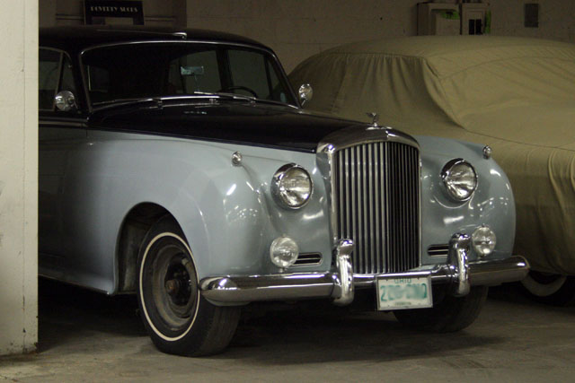 |
I do not yet know if the 6.23L V-8 engine will turn freely. The plan is to squirt sewing machine oil into the cylinders and allow that to soak in while I overhaul the brakes. Perhaps some cleaning and polishing is in order as well? And yes, the wheel covers are in the boot. |
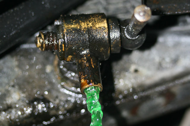 |
Today's session began by freeing the cap on the header tank and then opening this nice brass tap underneath the radiator. It is similar in design but smaller than the ones on the Wraith. There are also two additional taps, one under neath each cylinder bank. The Silver Shadow gets by with one lame tap on the radiator that looks like a period American automobile. Only about three quarts came out but what did come out had no sediment or oil in it. Sediment probably settled out already. |
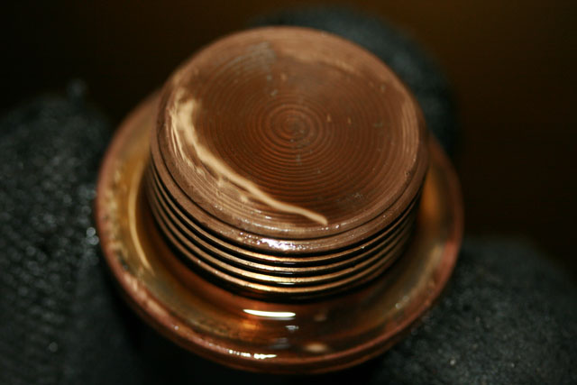 |
Drained the old engine oil out. Nothing untoward suspended in the oil. I suspect Willard had the oil changed immediately prior to storing the car. If you look carefully you can see the tool path in the drain plug from the lathe on which it was made. |
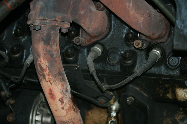 |
With the right front wheel off and the inspection cover removed the right side (A-bank) of the engine becomes visible. The side of the engine is much cleaner than I would expect. Usually the rocker gaskets have leaked oil all over everything - starter motor in particular. Also, no evidence of leakage from the weep holes in the block. Not shown: front engine mount looks like it's seen better days. |
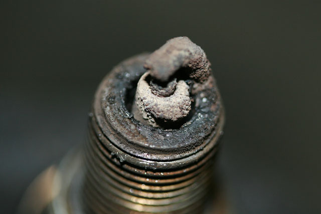 |
Spark plugs look pretty good, not oily anyway. Engine was running nicely when it was stored 15 years ago. |
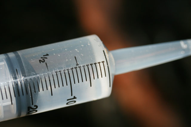 |
Each cylinder on the A-bank received 20 ml of sewing machine oil: highly refined and very lightweight (~10W) but offers actual lubrication when the engine turns over. |
 |
December 13, 2009 We have the car positioned here in the day bay for additional ministrations in the engine department. |
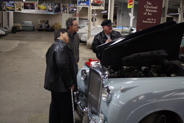 |
My friend Mark came along with me today and local RROC luminaries Gary Rock (Chairman) and Maryann Rock (Secretary) stopped by to check out the new car. |
 |
The old air intake trunk has been removed and thrown in the trash - cracked and brittle with age. For folks not so familiar with these engines: this is the left side of the engine. The large cylindrical object on the left is the choke housing which feeds a pair of SU constant velocity carburetors. On of these carburetors can be seen in the center of the photo |
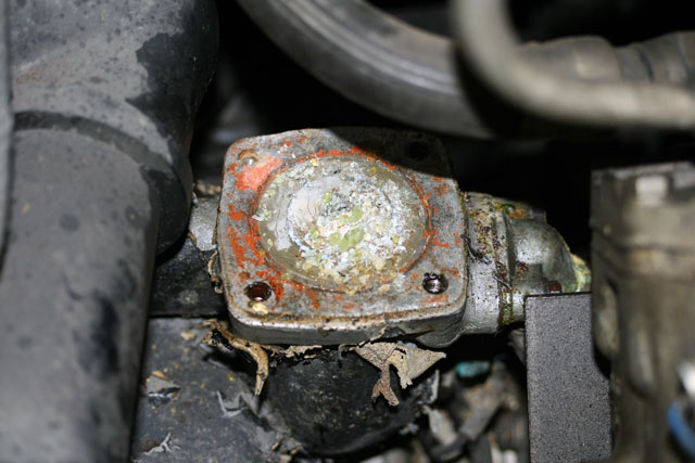 |
Removed the upper radiator hose and top half of the thermostat housing. Most of this corrosion easily wiped away but I still don't have the thermostat out. It's going to soak in PB Blaster overnight. |
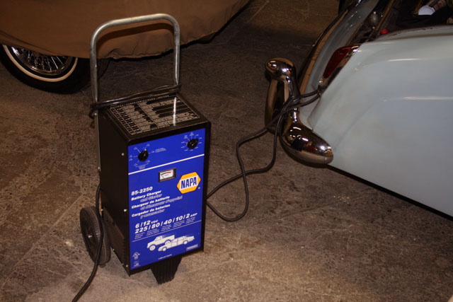 |
I hooked up Mike's charger to the battery leads and set it for 12V @ 2 amps and worked my way up. Thus, if there was a short it might not instantly turn into a full blown fire. The Halon extinguisher was at the ready, but to my great relief almost EVERYTHING works: brake lights, headlights, side and tail lights, fog lights, panel lights, dome light, license plate light, and reverse light. The radio works, as well as the fuel gauge and low fuel light. Horn is so-so and the left hand blinker relay is stuck on. |
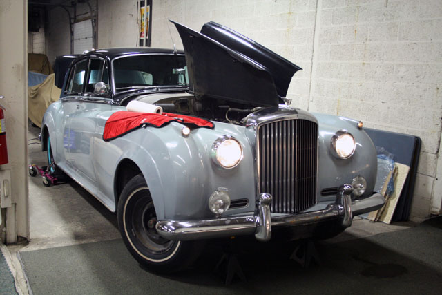 |
The fuel pump seems to be down for the count. The wiper switch is frozen so I did not test the wipers. All of the electric windows worked except for the left rear which seems to be stuck in its tracks rather than a dead motor. The A/C compressor clutch seems to work but I need to read the service manual some more before I can say that the blower motors are fully functional. Also changed the oil filter and added five qts. of 5W-30 (purposely thin) oil and injected sewing machine oil into the cylinders on B-bank. |
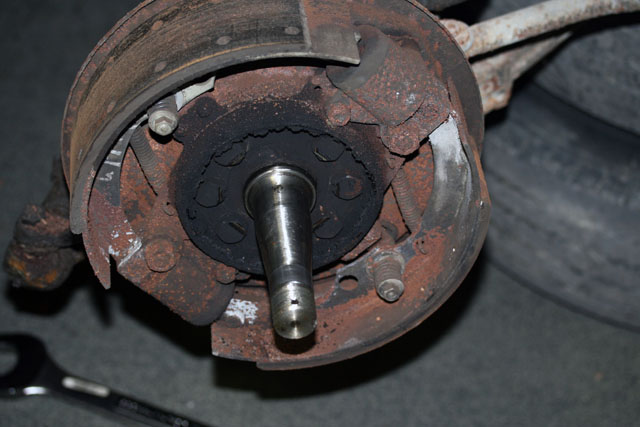 |
December 16, 2009 This is the right front brake assembly with drum and hub assembly removed. After undoing the two hydraulic connections at the top (not shown) and the six hex head screws in the center... |
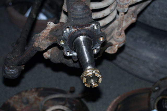 |
the entire brake assembly comes off leaving only the stub axle. The other left side brake assembly was also removed today, but you get the idea. The wheel bearings appear to be in reasonable shape and there was an adequate amount of grease present. Brake shoes appear to have a reasonable amount of lining left before they reach their 1/32" (from the rivet heads) service limit. |
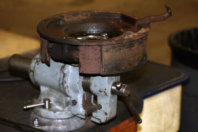 |
December 17, 2009 To remove the piston assemblies, one needs access to the bolts holding them to the carrier plate. To do this, the backplate needs to come off which is held to the carrier with 8 2BA set screws. |
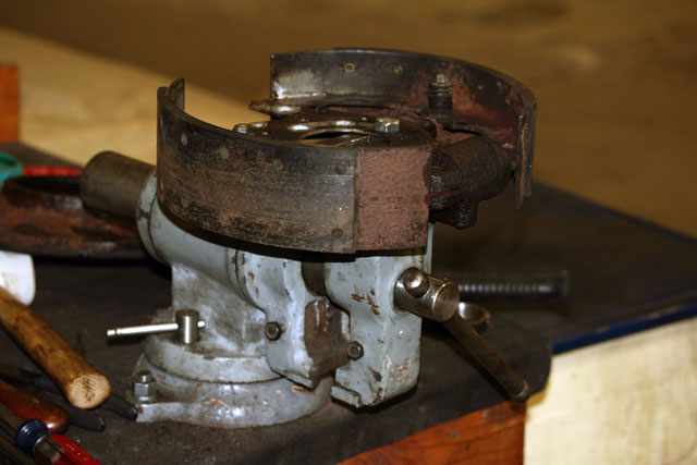 |
The assembly minus back plate is held firmly in the vise with two 1/2-in. bolts from the hardware store. |
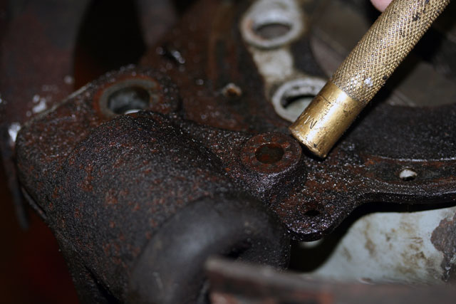 |
With the piston's mounting hardware removed, a brass drift is employed to knock the pistons off of the carrier plate. |
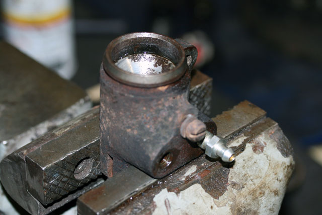 |
Next, each pistons is gently held in the vise with bleed screw in place so that compressed air can be applied in the other threaded hole in hopes of removing the piston. Note: the pistons can fly off at great speed with 150 psi of air pressure. Hold a large shop rag over the piston and for Heaven's sake don't point it at anyone! |
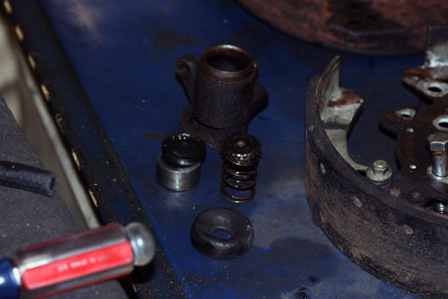 |
This one readily came apart with a little penetrating oil. The remaining three required heat and plenty of persuasion. Clearly all of this work was absolutely necessary. With one sluggish and three seized pistons, the car had virtually zero front brakes! |
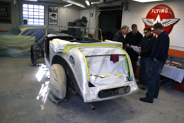 |
Happy New Year! Every month we have a cars and coffee event at the garage where I keep my cars. This time we got to talking with Paul Bearman (r) who co-owns 203 Custom Car Works. Paul and business partner Scott Mueller are the ones that painted my Silver Shadow. They now have my friend Todd's 1938 4-1/4L Bentley with Cockshoot drophead body. Here the lunch crew Bram, Roy and Buck (l-r) weigh in on possible color combinations. |
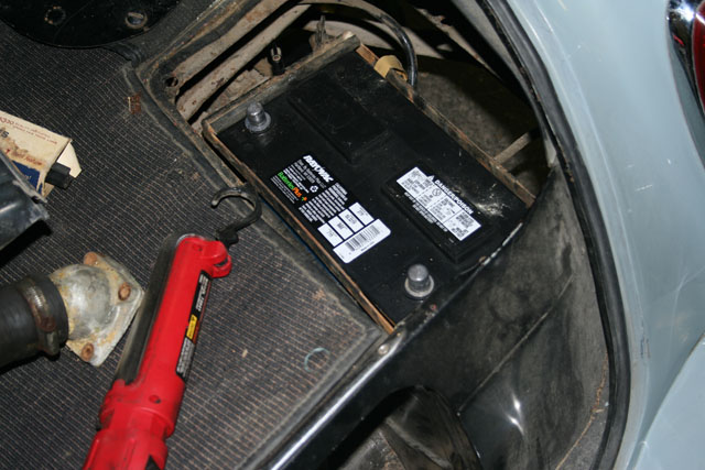 |
January 3, 2010 Looks like I ordered the wrong battery. This is a 27F which fits correctly, but the terminals are reversed. (And yes, oh pedantic ones, the battery terminals should be aloung the outside edge.) If the dealer won't let me swap, I believe this will fit the Silver Shadow. |
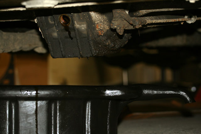 |
The rear end was full of respectably clean gear oil. I drained and refilled with fresh stuff. |
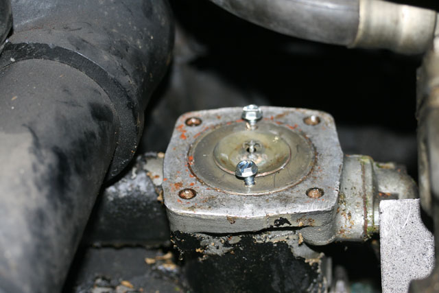 |
January 4, 2010 Clearly I need reading glasses. I used self tapping screws in the holes of the thermostat in order to lever it out. If I could focus properly or bothered to read the service manual I would have realised the holes were already tapped just for this purpose. They should be 2BA or 3BA, they made it both ways. If I reuse the thermostat, I can drill it out and tap to 2BA because it appears to have been 3BA. |
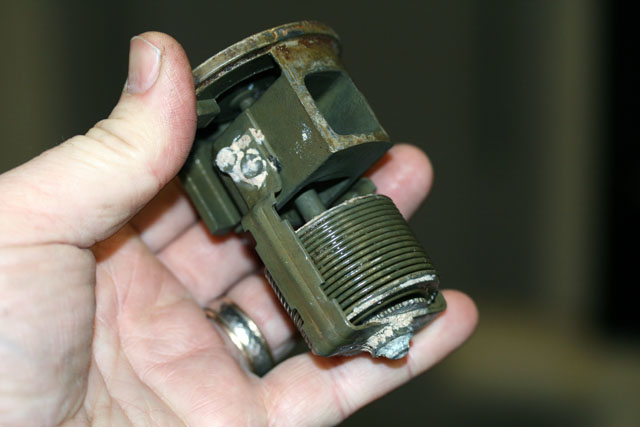 |
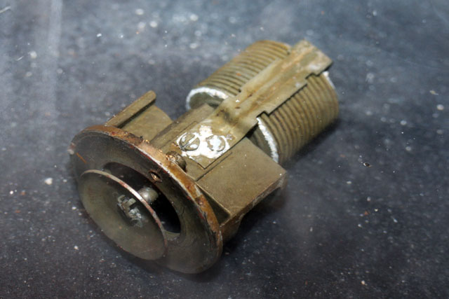
This is not a stamped pedestrian thermostat. The valve body is machined and the whole thing feels very MIL-spec. |
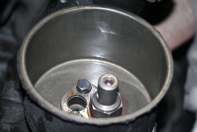 |
The power steering reservoir was very clean although there was no filter present. I wiped it out and installed a new filter. |
 |
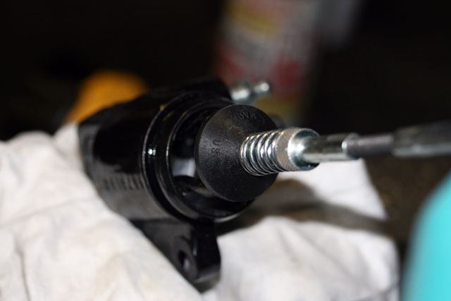
January 5, 2009 Looks like the thermostat can be reinstalled. It opens repeatably at the prescribed 172F. It is shown here in the open state in a pot of very hot water. |
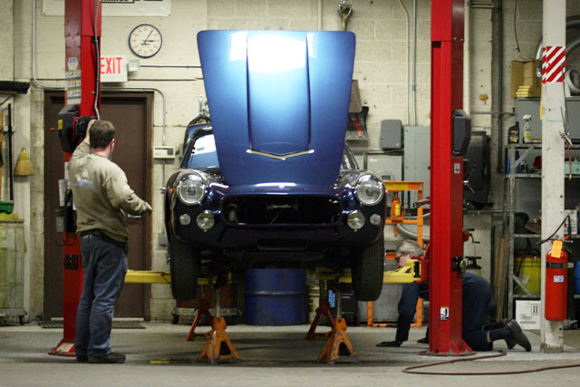 |
The Bentley is not the only interesting restoration going on in the garage. That's Mike on the left and Peter on the right. The car is Peter's Vignale-bodied Maserati. Mike and Peter are usually around when I am working on the Bentley and offer plenty of useful advice. |
 |
January 7, 2010 Thursday turned out to be brake honing day. About two minutes each worked out nicely. |
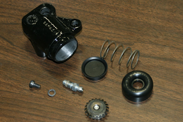 |
This is one of the front brake pistons ready for reassembly. I used Permatex brake caliper grease to lube the chrome-plated piston (not shown). |
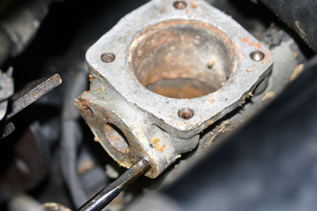 |
With the spark plug holes just about the only exception, the Bentley's 6.23L engine is Heli-coiled at the factory. While trying to replace the bypass hose, one of the Heli-coils came out. This not an uncommon occurrence when working on elements of the engine that handle coolant. Fortunately, I have a complete 1/4-28 Helicoil kit for use on the Silver Shadow which has a similar engine. This photo shows the offending threaded hole being cleaned with the supplied tap prior to installing a new insert. |
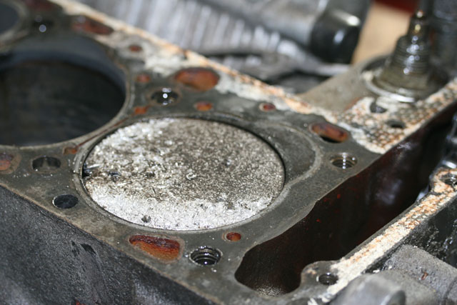 |
January 12, 2010 This is not the Bentley. Mike started to rebuild the engine in a clients' 1970 Mercedes-Benz 280SL. The rings in cylinder number one broke up and the car was driven for some time after that. Unfortunately, the engine is already bored out to maximum so the block is scrap. |
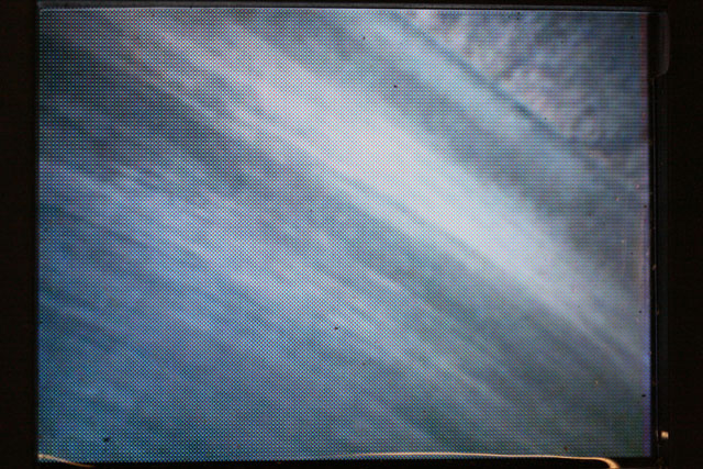 |
Speaking of Mike, I borrowed his borescope to peer in through the spark plug holes to assess the condition of the cylinders and pistons. Pistons appeared fine, some had a fairly high accumulation on carbon. In general, the cylinder walls looked fine with hone marks visible. |
 |
In the two cylinders that had a valve open to the atmosphere however, they're a bit rusty. I injected more oil in the cylinders, this time ATF and plan an attempted hand turn of the engine in a few days time. |
 |
I removed the float bowl cover on the A-bank carburetor. The large fiber gasket has disintegrated but the float needle assembly is clean and functional. The entire float chamber was devoid of contamination and bone dry. This bodes well. I need to check the diaphragms in the carbs and get the fuel pump working but it does not appear the fuel system will be a sludged up nightmare. |
 |
Note the little splined hinge pin to preclude rotation of the pin in its boss. |
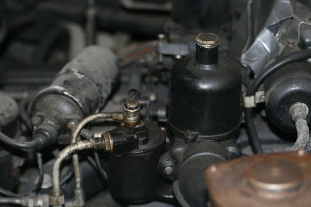 |
In case you were wondering, the float bowl is the black cylinder with two pipes coming out of it. I also replaced the lower radiator hose today. Although it took two hours to do so due to tight quarters, I am glad I did. The hose clamps on the old hose were not tightened the last time it was replaced. |
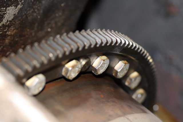 |
Well, there's something in the number thirteen because on the 13th, I removed the lower half of the bell housing and attempted to turn the engine. No movement. Seized. Time to go home and just effing cry. Fortunately, Mike noticed that the starter pinion was engaged. Hmmph, a glimmer of hope. On the 14th, I removed the almost seized starter motor and now the engine now turns free! Whew. |
 |
My good friend Dave Cunningham, carburetor guru and President of the OCD Cleaning Society came by to help. His chosen assignment is to remove the carburetor choke and associated linkage as a unit, clean everything up and most likely replace the diaphragms. The stove pipes from choke to the exhaust manifold really rust up a storm on Silver Shadows but these came off with ease. |
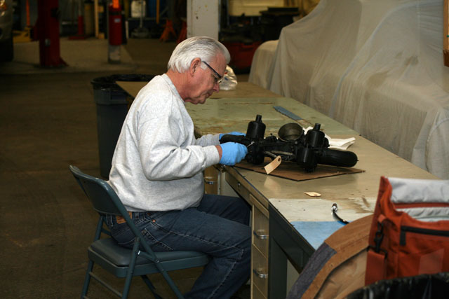 |
Here's Dave getting down to business. |
 |
Meanwhile, I pulled the rocker covers and found an outrageously clean engine. My Silver Shadow sure doesn't look like that on the inside. After taking the photo, I poured motor oil over the valvetrain to get everything lubricated |
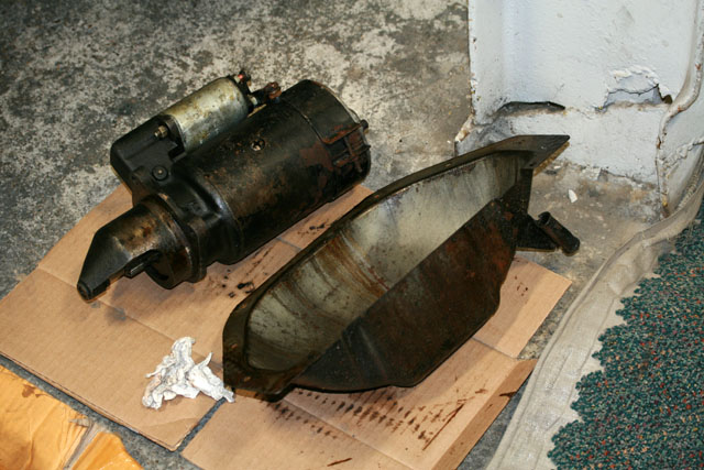 |
I neglected to photograph the rather large and heavy Lucas starter motor. Here it is shown next to the lower bell housing. |
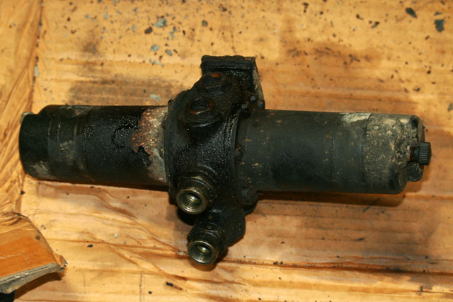 |
While Dave quietly tinkered away on the carburetors, I removed the SU double-ended fuel pump. Since a new pump is $300 and the rebuild kit is $50 (and Dave's labor is free), rebuilding the fuel pump will be Dave's next project. |
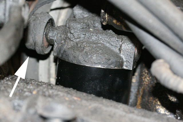 |
The oil pressure transducer is located atop the oil filter housing... |
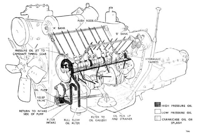 |
It measures the pressure exiting the filter on the way to the main bearings and lifters (a.k.a. hydraulic tappets). The plan is to temporarily remove the pressure transducer and hook up an external pressurized source of oil to get everything lubricated prior to any attempt to turn the engine over at starting speeds. |
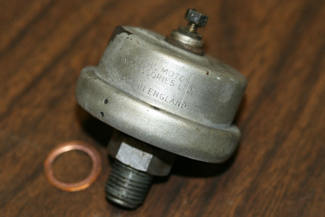 |
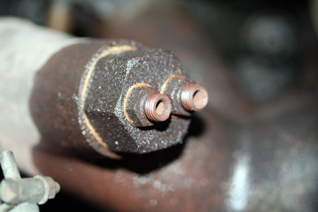
Now cleaned and removed, the transducer has a thread pattern that initially gave me pause. Based on my Wraith experience and a hunch, I looked up the British Standard Parallel Pipe specs and found my answer. |
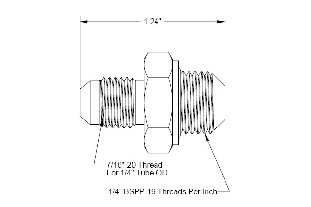 |
Even better, I found a $6.33 brass adapter that I can use to attach the hose of Mike's oil pressurizer directly to the oil filter housing. I love McMaster-Carr! |
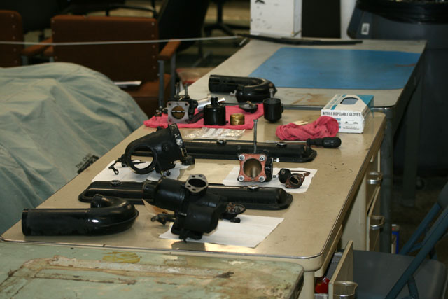 |
Meanwhile, Dave made great progress today. He's about 40% done cleaning everything. Since some of the carburetor elements are matched, he has been particularly careful to keep the parts of the two carbs in separate piles. |
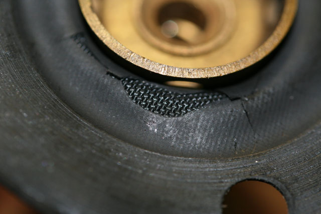 |
Dave removed the diaphragm/jet assemblies from the carbs today and it appears that it was indeed time for an overhaul. One of the old diaphragms is shown here: brittle and cracking. |
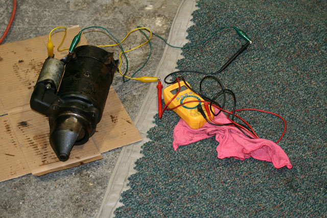 |
The starter motor tested okay for continuity accross the brushes and commutator, but failed to run when hooked up to a power supply. It appears to be very stiff. Rather than dork with it, I plan to take it to Ted's Auto Electric down the street and let him have a go. |
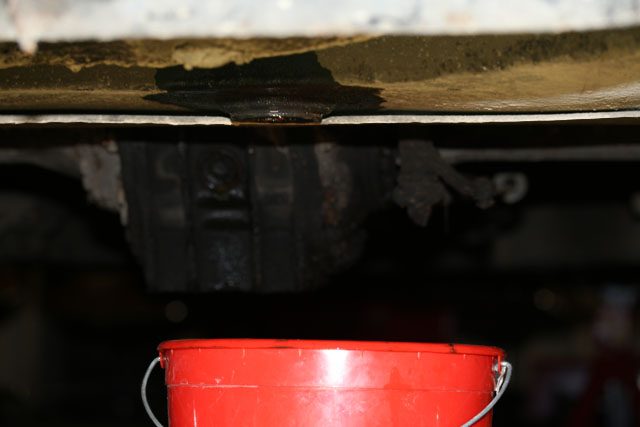 |
You know how fuel tank drain plugs are always seized in place? Not so this time. This one actually came out, along with about 2 oz. of old gasoline and negligible sediment. Dodged that bullet. |
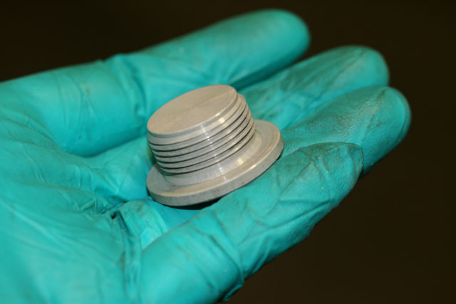 |
This is the "alodized" aluminum plug. |
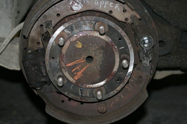 |
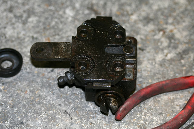
On to the rear brakes. The right rear drum had not been removed when we trailered the car last month because this was the only wheel that turned freely. As a result, it took a bit of effort to remove today. The rear brakes have a double acting piston (l) combined with a mechanical expander. The adjuster is on the right. |
 |
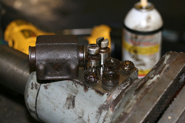
The piston and expander assembly came off readily once the hydraulic line and one 2BA set screw was removed. |
 |
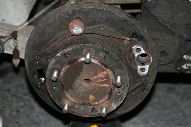
Piston removal is also easier on the rear brakes. Those large slots allow you to spin the pistons and work in penetrating oil prior to hitting it with pressurized air. Once one piston is out and the spring and spreaders are picked out, the other piston can be tapped out with a brass drift. |
 |
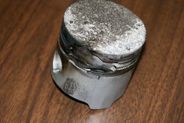
The carrier and back plates are now stripped of just about everything. I understand the rear hubs are a real bear to remove. With the hub in place, the carrier and back plate will have to be refinished in situ. |
 |
January 19, 2010 Remember that Mercedes engine Mike's working on? Piston looks even worse now that it's out. |
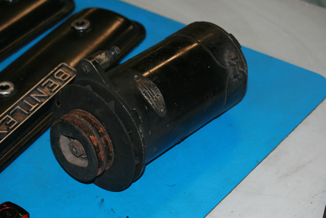 |
I removed the generator and took it and the starter motor to Ted's Auto Electric in Ypsilanti to have them refurbished. |
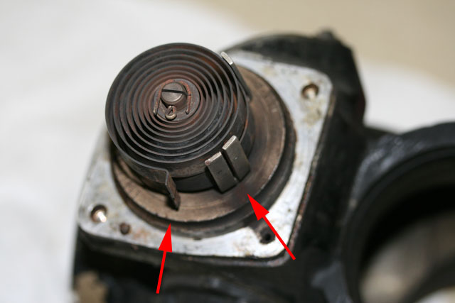 |
This is the thermocoil on the choke housing. In order for the coil to turn the shaft as it is heated, the tabs have to be seated in the slot. It is unlikely that the car was getting any cold start enrichment at all. Must have been hard cranking! |
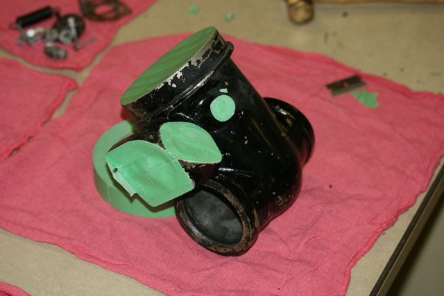 |
Dave's been cleaning each individual component in the choke/carb assembly. This is the choke housing minus all of its components almost ready to be repainted. |
 |
Meanwhile, I got the last of the brake cylinders apart. Pistons look great. Despite the fact that all but one of the wheels had seized brakes, I did not have to replace any pistons or sleeve any cylinders. |
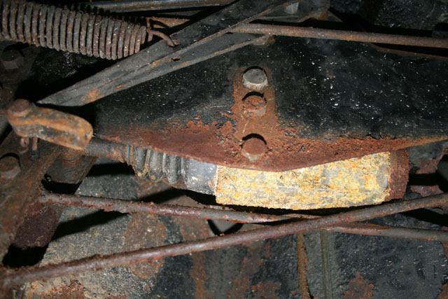 |
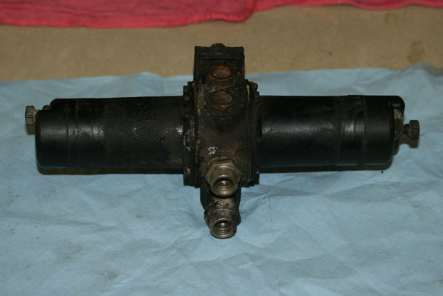
On to the master cylinders. They can be found underneath the car on the right side about half way between the front and rear wheels. There is a massive convergence of levers, rods and springs in this area. There are two cylinders. The lower one is visible and the upper one is stacked on top of the lower. Having read the relevant service manual section twice, it is still a fiddly, slow task which is made less pleasant with dried brake fluid, rust and clay raining down in my eyes. |
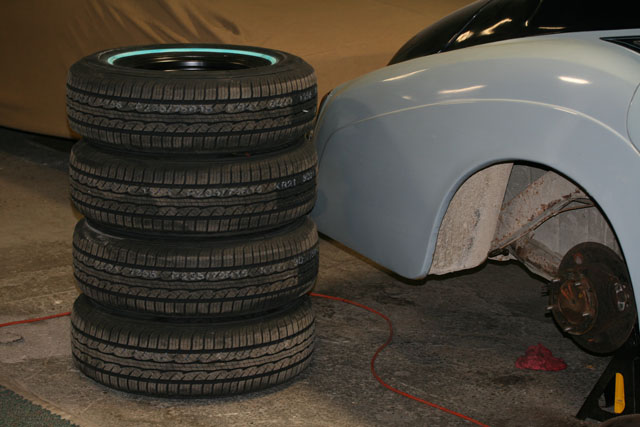 |
September 22, 2010 The remainder of the rims have been sand blasted and powder coated. Here they are with new tires mounted. |
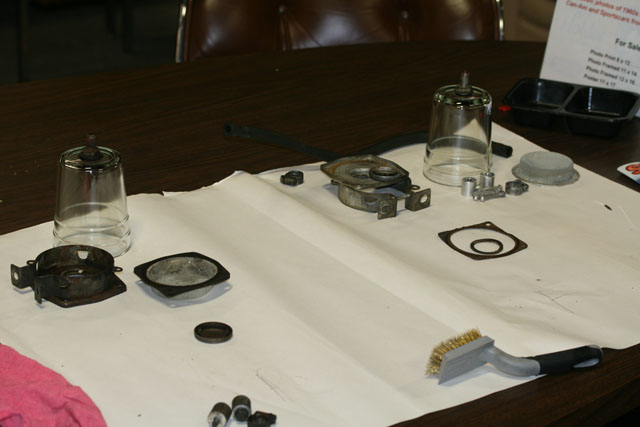 |
I'm on day two of master cylinder removal. Meanwhile Dave has moved on to removing and cleaning the two brake fluid reservoirs while we wait for carb parts to arrive from Burlen and choke parts from Albers. Rest assured, the glass reservoirs did not look like that when they came out of the car! I'm going to have a bunch of parts cadmium plated next week including the reservoir lids. |
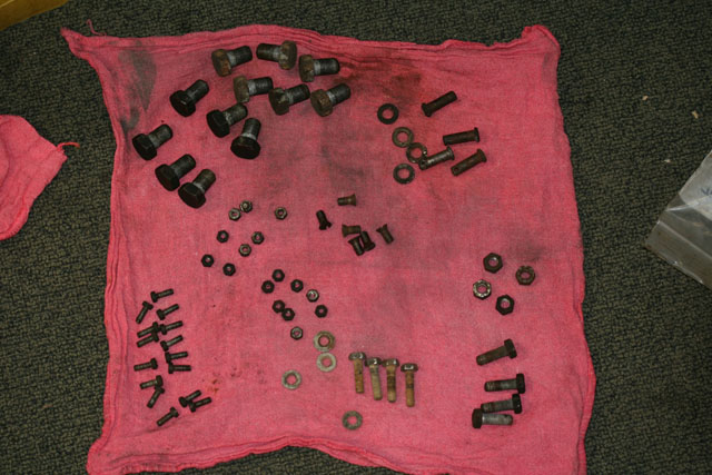 |
I took this photo to inventory the hardware (front brakes and thermostat stuff) that I was about to dump in Mike's vibratory tumbler. The tumbler has plastic beads and a mixture of Simple Green and a cleaner made by Loctite. |
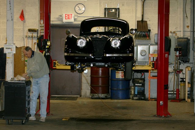 |
Jack's in today working on his XK 120 fixed-head coupé frame off restoration. |
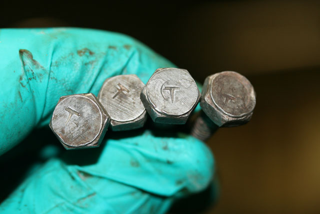 |
Once out of the tumbler, I noticed that the thermostat screws have a "T" stamped in them. They must be the originals. That's pretty incredible, because that joint is notorious for dissolving hardware. |
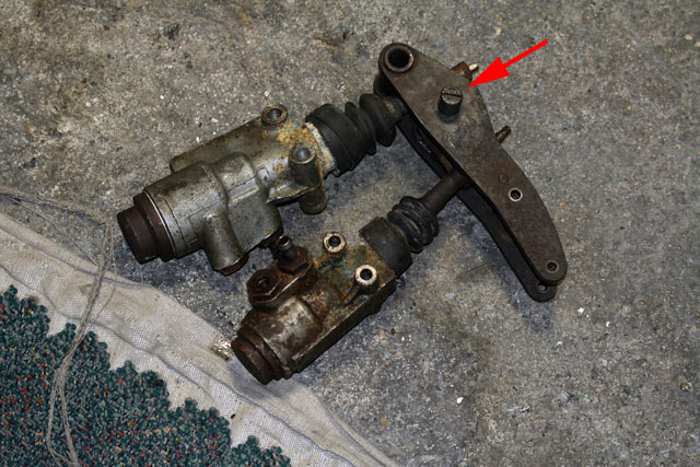 |
I finally liberated the master cylinders from underneath the car. Turns out that if I had pulled the pin marked by the red arrow, I would have had the job done yesterday. |
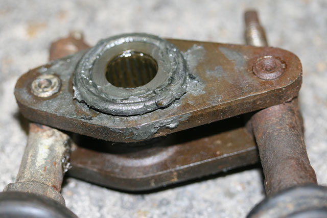 |
The pin releases the needle bearing assembly shown partially disassembled in this photo. |
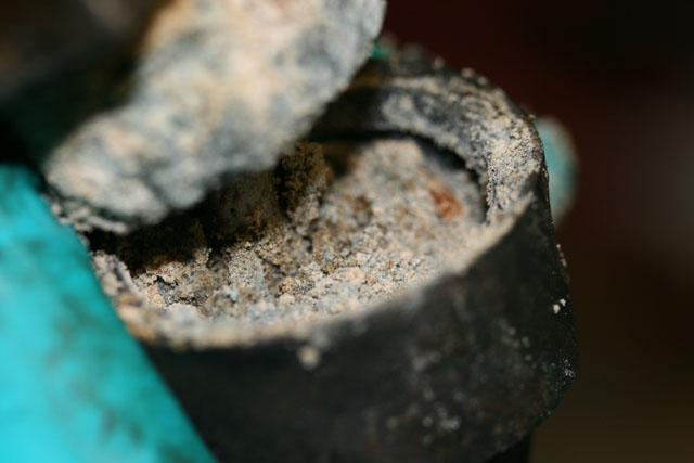 |
The master cylinder boots were packed with dried brake fluid. |
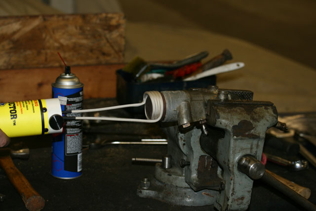 |
Mike broke out his newest toy - an inductive heating element. We used this to heat the threaded end cap on each of the master cylinders. Then a mere 200-300 ft-lb or so is all that is needed to remove the cap. The small unit takes a 1-3/8 inch wrench and the large one takes a 1-1/2. |
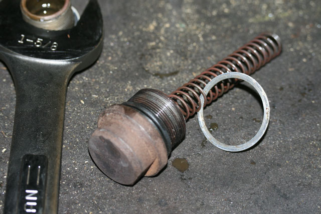 |
Here's the larger of the two cooling off on the bench. |
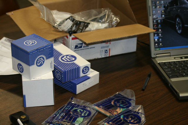 |
January 25-26, 2010 All of the carburetor, fuel pump parts arrived from Burlen in cool SU boxes. The Albers parts also arrived. Albers included a free Bentley mouse pad in my order. I gave it to Dave and he seemed pretty darned tickled. |
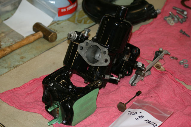 |
Dave wasted no time putting the B-bank carburetor together. As you can tell he's done quite a bit of detailed painting as well. |
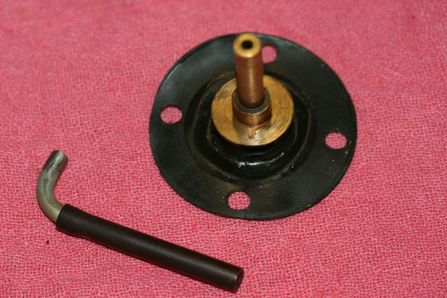 |
One curious bit that required the "phone a friend" option. The carburetors as installed each had an inside pipe running from the float bowl to the underside the jet. The new overhaul kit includes no such provision. The new jet will not accept the old tube. The replacement spring on the underside of the diaphragm makes no provision for the tube either. Guru Dan Docherty indicated that the updated kits eliminate the tube entirely and he hasn't seen a Crewe V8 with intact tubes in a long time. |
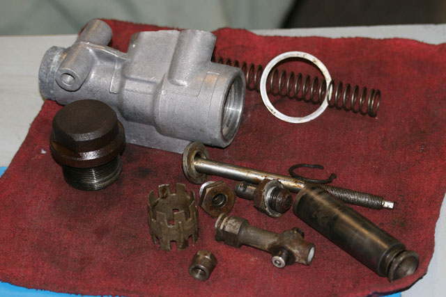 |
The master cylinders have been completely disassembled and cleaned. |
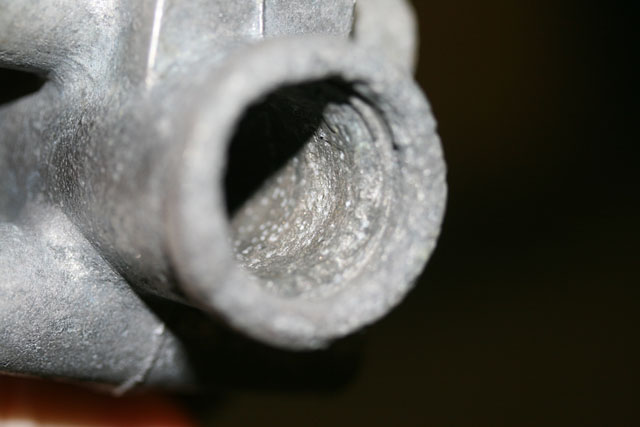 |
The majority of the master cylinders' bores look fine except where the seal sits 99% of the time. This is heavily pitted and will require sleeving. I will box the two castings up tonight and send them off to Apple Hydraulics in Calverton, NY. |
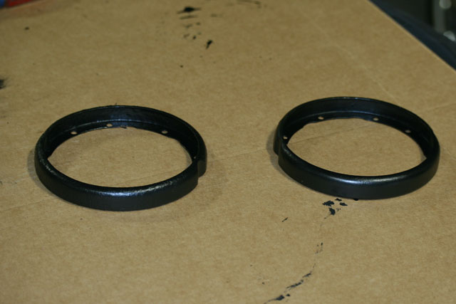 |
Also had occasion to wire wheel and paint the grease carchers on the front wheel hubs. |
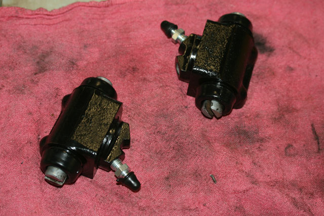 |
Mike finished bead blasting and repainting my rear brake cylinders. These looked great, I lightly honed them and reassembled with new seals. |
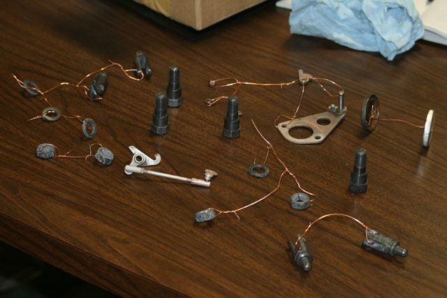 |
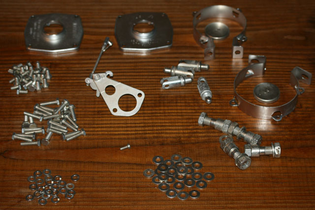
Here are a number of front brake, brake reservoir and carburetor parts wired up ready to be replated. |
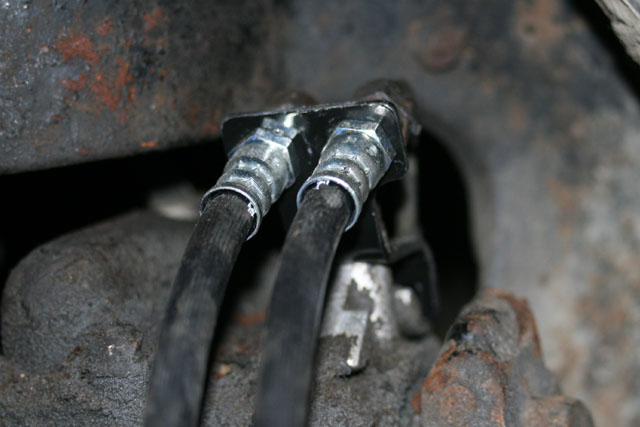 |
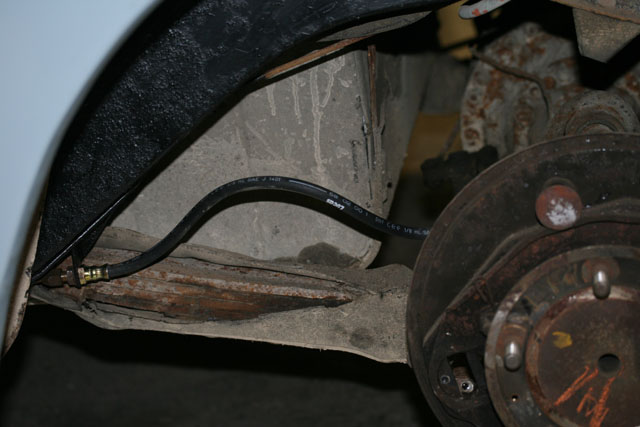
Installed the front flexible brake lines on both sides. |
 |
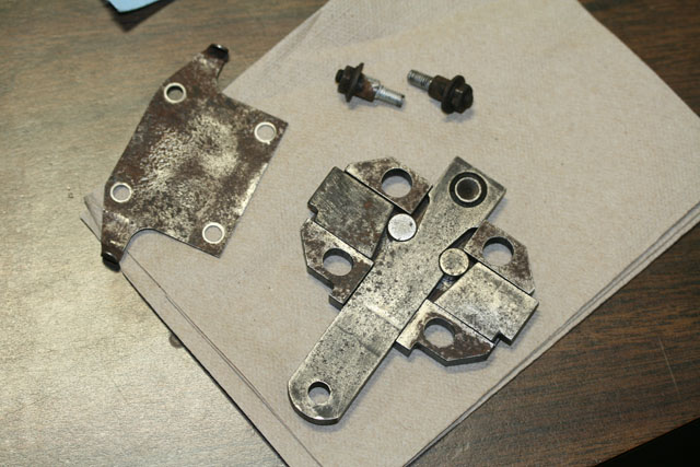
There's only one rear flexible line. I scraped and painted the frame in the general area of the brake line connection to make my life easier later on. |
 |
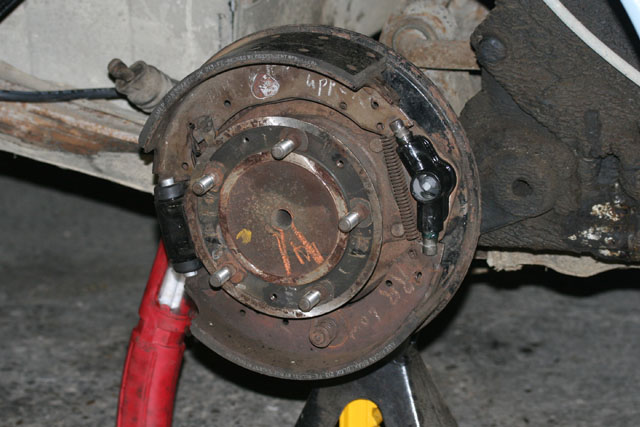
This is the mechanical expander which serves as a back-up to the twin cylinder on each rear brake. It is liberally greased prior to reassembly to the side of the brake cylinder. |
 |
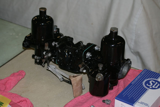
Here's everything installed on the right rear, at least until I realize I forgot something. Dave's made great progress on the caburetors and has in fact begun reassembly into the complete unit. I neglected to photograph it in my headlong rush out of the garage Friday afternoon. |
 |
Dave's taken the carburetor/choke assembly about as far as it can go because we are missing a few parts: a new choke diaphragm which is back ordered and the choke linkage which is being electroplated. |
 |
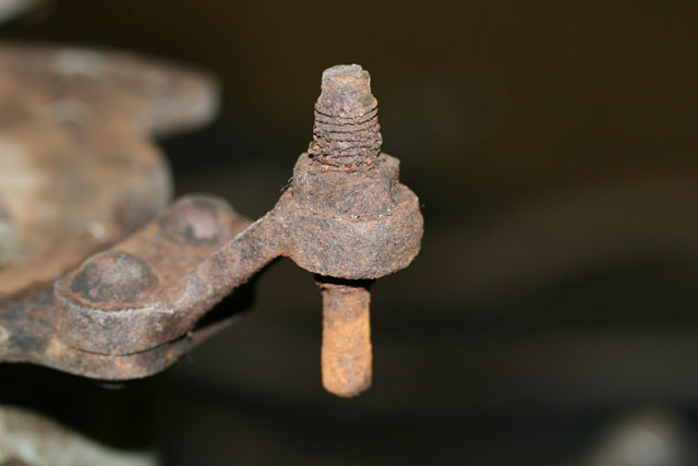
The next Dave project will be to overhaul the fuel pump. Other news: After three days of trying, I finally removed the 2BA cheese head screw holding the cover plate to the carrier plate on the left rear brake. With repeated applications of heat, lubrication and force, I got the clevis pin removed from the left rear brake mechanical linkage. Now I will be able to remove the entire equalizing assembly that runs along the back axle. |
 |
February 2, 2010 The steady posts that support the "shake back stops" on the front brakes are badly corroded and have no provision left for adjustment. (The adjustment squares the face of each pad to the drum.) The better part of the morning was spent politely coercing them off of the carrier plates. Post 55 Parts which is a small U.S.-based company specializing in Rolls-Royce Silver Cloud and Bentley S parts has reproductions for $5.00 ea. |
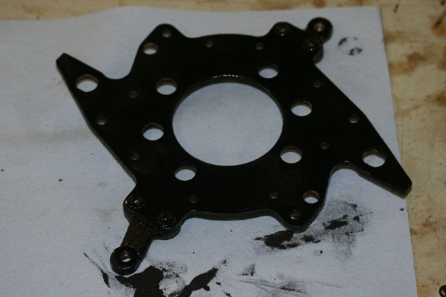 |
The front carrier plates have been wire brushed and painted. |
 |
Left early to pick up the plated parts (and also work on editing a Hooper coachbuilding article for the Flying Lady.) Other
news: Today was Dave's day off. No progress to report on the fuel pump. Pete Kohnken stopped by, gave me a bunch of very useful brake tips, parts and specialized tools and then bought me lunch at the Sidetrack. Can't argue with that! |
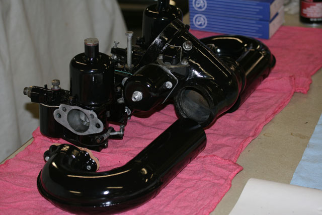 |
With the re-plated choke linkage now in place, all that's left is the choke diaphragm. |
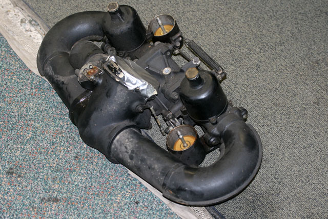 |
You may recall this is what it used to look like. |
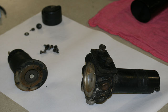 |
Dave moved on to fuel pump, which is a double-ended SU. These were used on a variety of British cars including every Rolls-Royce and Bentley from the 25/30 and 4-1/4 litre of the mid-Thirties right thru to Series I Silver Shadows of the Seventies. Dave has wisely chosen to rebuild one side at a time, that way he can use the other side as a guide. |
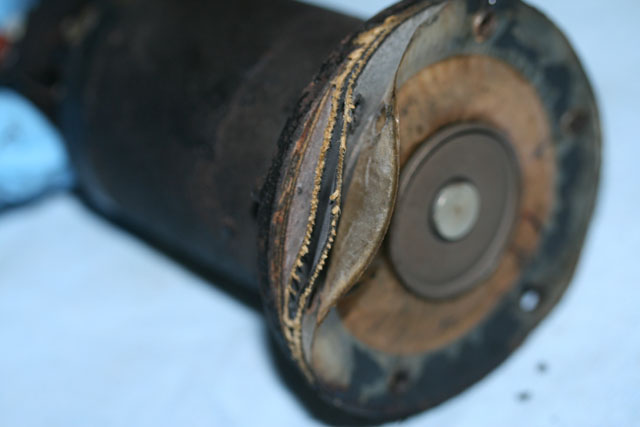 |
The diaphragm has delaminated dramatically. |
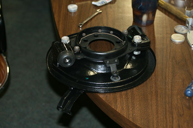 |
Meanwhile, I started to reassemble the front brakes which are assembled as mirror images of each other. All of the shoes in the front are oriented as to be "trailing" in the direction of forward rotation. This is the right front. |
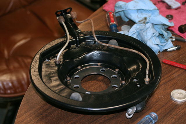 |
I had broken one of the hard brake lines during disasssembly. (Not a bad batting average really, one casualty out of thirteen connections. I reused the fittings and fashioned a new line from 3/16 Bundy tubing forming double flares at each end. |
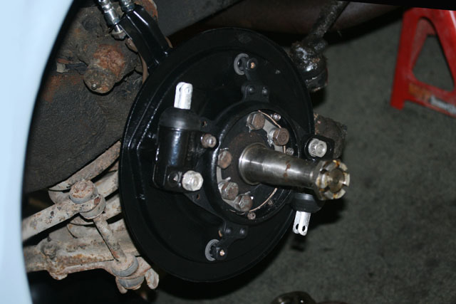 |
Here is the left front back plate with excluder, gaskets, locking tabs, and cylinders in place. The steady posts on order from Post 55 Parts will have to be installed before the brake shoes go in and everthing is adjusted and tightened. It's nice to get all of these parts out of their bags and back onto the car. Just the portion of the assembly that you see here represents ~50 parts all of which had to be replaced or cleaned, plated and/or painted. |
 |
February 4, 2010 Mike and Ed had an eventful day working on a Porsche Boxter S. It had all manner of issues including low oil pressure and clutch judder. Upon further investigation, the oil sump had massive amounts of metal bits in it. |
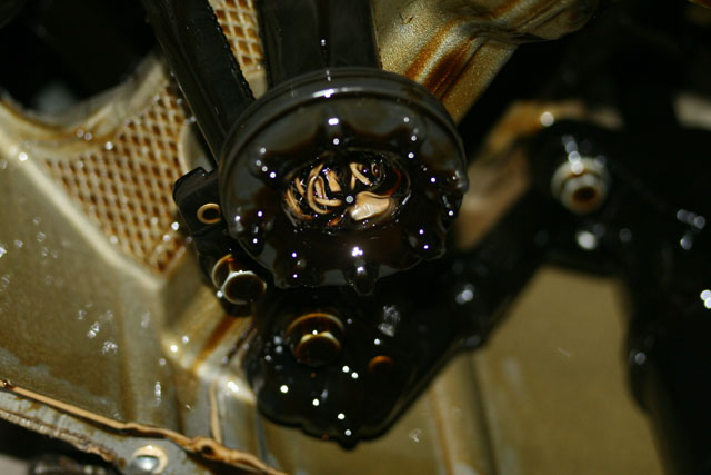 |
Root cause? Overzealous RTV application on a previous sump replacement (by some other shop). The excess eventually separated from the joint and got sucked in the oil pump pickup clogging it. Ed called it "RTV worms". |
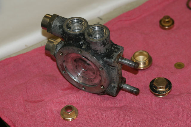 |
Meanwhile Dave had the pump valve body stripped cleaned and ready for reassembly. |
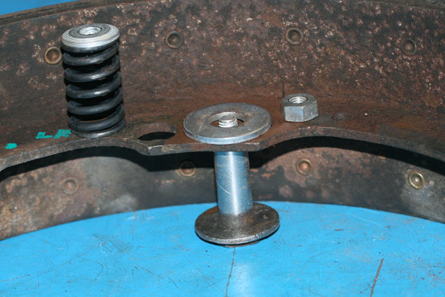 |
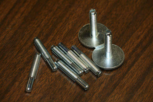
I removed, cleaned the "shake back stops" on each of the six brake shoes that use them. Also removed the old "steady posts" from the rear brake carriers. The new steady posts arrived from Post 55 Parts. I should be able to completely reassemble all four brakes tomorrow if time permits - need to clean things up in preparation for Saturday's open house. |
 |
February 5, 2010 The steady posts were waiting for me when I arrived at home last night. |
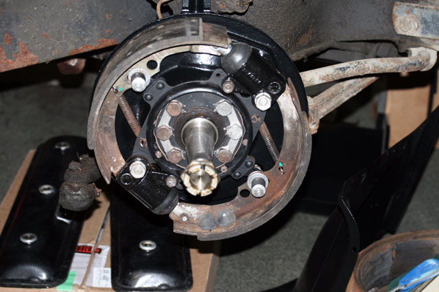 |
This allowed me to finish assembling the front brakes |
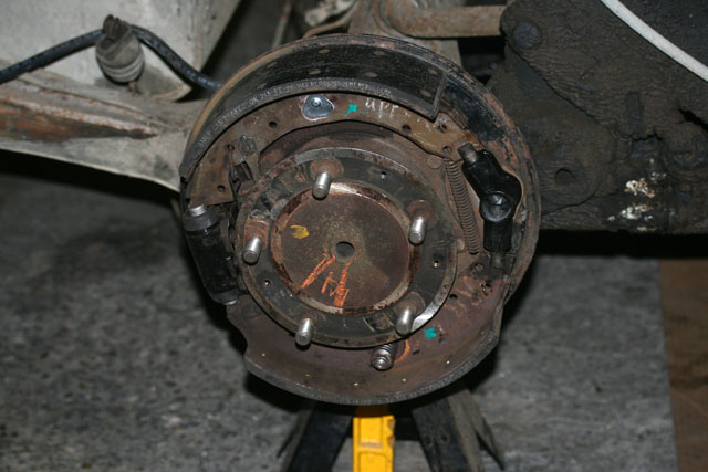 |
As well as the right hand rear brake. The left rear needs one part on its way from Flying Spares. |
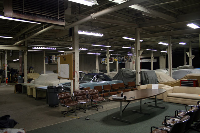 |
The monthly open house for the garage is tomorrow. I spent a portion of the afternoon cleaning up the general area. I even vacuumed!
|
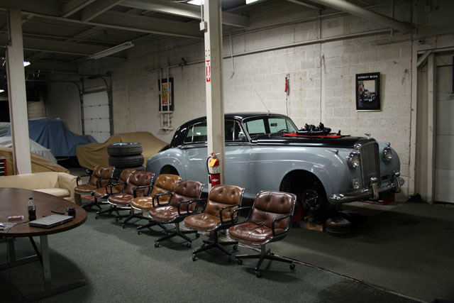 |
You can see Dave's completed (except for the choke diaphragm) air-fuel charging assembly resting gently on the bonnet. |
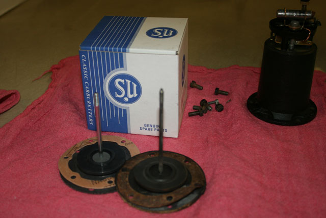 |
Turns out I bought the wrong fuel pump overhaul kits. The new diaphragm has a threaded rod that's a full inch shorter than the old one on the left. It won't work in this application. Fortunately, I believe these are the correct kits to overhaul my Silver Shadow fuel pump so I'll just put them on the shelf until needed. |
 |
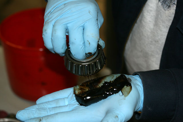
The front wheel bearings (right side shown) are enormous, understressed and perfectly fine to put back in service. |
 |
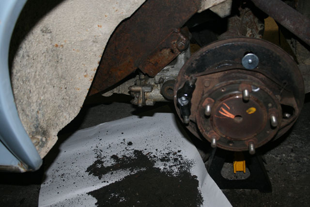
Dave is shown here repacking them with grease. |
 |
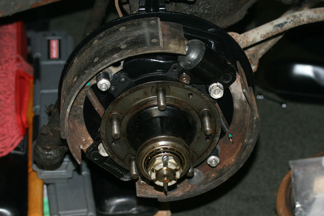
Dave got busy cleaning things. He knocked about five pounds of Ohio clay off of the left rear shock damper. |
 |
Meanwhile, I installed the right front hub with repacked bearings. |
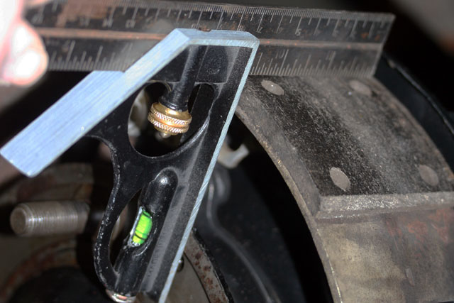 |
Next the "steady posts" are adjusted so that they are perpendicular to the wheel mounting face of the hub. |
 |
February 9, 2010 We got going right away this morning because there's a fairly big snow storm closing in on us. Before Dave took off at 10:00, he cleaned the other rear shock damper. Then he set about cleaning and reconditioning the "rear brake equalising gear". Unfortunately, I did not get a photograph of it before he took it home to work on it there. |
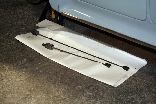 |
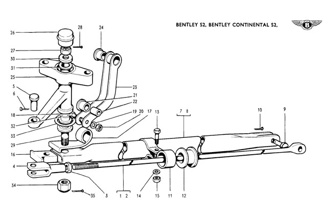
These are the two actuating rods that run parallel to the rear axle from the "equalising gear" to the mechanical expanders in each rear drum. |
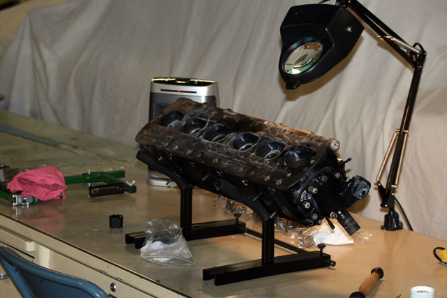 |
After assembling the left rear brake and adjusting the "steady posts", I pondered the status of the project. We're waiting on seals for the brake reservoirs, the choke diaphragm, some 2BA screws for the brakes, the sleeved master cylinders and correct pump diaphragms. All of this more or less halts progress on most fronts. The sleeved master cylinders shipped this afternoon, so that's good. Meanwhile, I started the process of valve lapping and reassembling the cylinder head to the 1939 Wraith. |
©2009-2010,
Sherbourne Mews, LLC
Click here to contact the webmaster.